YAHMS: Temperature Probes

My wireless temperature probes work by using an Xbee module to transmit readings from a TMP36 down to the Arduino base station. The XBees aren’t too cheap, coming in around £19 or $23 so I tried to be cheap and ordered mine from Sparkfun, I bought this XBee (series 1) with Chip Antenna and these breakout boards. I was intending to solder the module directly onto the board and didn’t take notice of what Sparkfun says about “please order the accompanying 2mm sockets (you’ll need 2!) and 0.1” headers below.” (these ones). Once I saw what a stupid idea it was to solder the module (means you can’t switch them around between boards, handy for testing and reprogramming) I ended up buying these headers from Farnell.
As mentioned, to take the temperature reading I’m using a TMP36, these take a voltage of around 3-5.5V as input and will output a voltage between 0-2.7V to indicate the temperature, which can be from -40 - 125°C. In the end I needed three of these for this project, two for another project and managed to kill a friends’ (or it was already dead) so I just bought 10 to make sure I had enough.
XBee modules require regulated 3.3V input, as I’m using the very basic breakout board that just breaks the pins out without adding any functionality I used a MCP1700(-3302E/TO) which accepts up to 6V. In my first order I just bought two, one for each temperature probe. The first time I tried one I managed to connect it to the batteries the wrong way round (in fact the wires on the battery pack were colour coded wrong!) which unfortunately killed the regulator. With this experience and a few others I’ve realised that for something that only costs £0.36 it’s never worth buying “just enough”, always get plenty. The data sheet for that part suggests putting 1 µF capacitors on the input and output, I had issues finding any with that rating that were cheap enough so ended up going with 3.3 µF capacitors. I eventually ordered 10 regulators so ordered 20 capacitors, might as well make sure I had enough to match!
In my initial experiments, when I was still using solar cells, I realised that although the regulator would regulate a large voltage down to 3.3V, if the input voltage was too low the output voltage would actually come out less than 3.3V. This gave me some interesting values when the XBee would just about continue to work, but the reference voltage against which the TMP36’s output was being measured would also drop resulting in temperatures shooting up as the batteries ran out!
I found the solar cells weren’t charging enough to power the XBee throughout the day, let alone through the night, so I decided to switch to batteries. I bought some of these 6xAA battery packs, I later realised I only need 4 batteries to power my regulator (and in fact 6 would be too many, I’d been thinking of Arduinos which would need more like 9V input) but it’s simple enough to short a few connections so that the packs work with 4 batteries instead. One problem I did have with these was that I didn’t get any connectors so I was trying to solder the wires directly onto the pack, this really didn’t work well because the plastic started melting before the solder did, so next time I’ll be buying some PP3 battery connectors like these.
To get around the issue of the voltage dropping below 3.3V I decided to use a voltage detector to detect when the input voltage was getting low and turn the whole circuit off, I used these TC54VN detectors to check for an input of at least 4.2V, meaning that my circuit should now provide between 4.2V and ~6V (4x1.5V AA batteries) to the regulator, or nothing. The voltage detectors I got are “Open Drain” which essentially means that when the voltage is above 4.2V, “VOUT” is floating, i.e. does nothing. When the voltage goes below 4.2V VOUT is pulled to ground. I actually expected VOUT to output the input voltage when the input voltage was high enough but it turns out I would need a TC54VC if I wanted that. The Open Drain version worked well enough once we figured it out (I had a lot of help from Adrian McEwen on this one). I’m using a transistor to turn on the voltage regulator. I pass the battery input to VOUT via a resistor and then onto base on the transistor via another resistor, this way the transistor is turned on, until the voltage drops and VOUT is grounded, short-circuiting the voltage meaning it doesn’t get to the transistor.

The picture above shows the circuit diagram as I was working on it, ignore the Arduino-style pins at the top and bottom. The two circuit diagrams should be just about the same, the higher one was supposed to be clearer. Here’s a fritzing diagram which should hopefully be more useful:
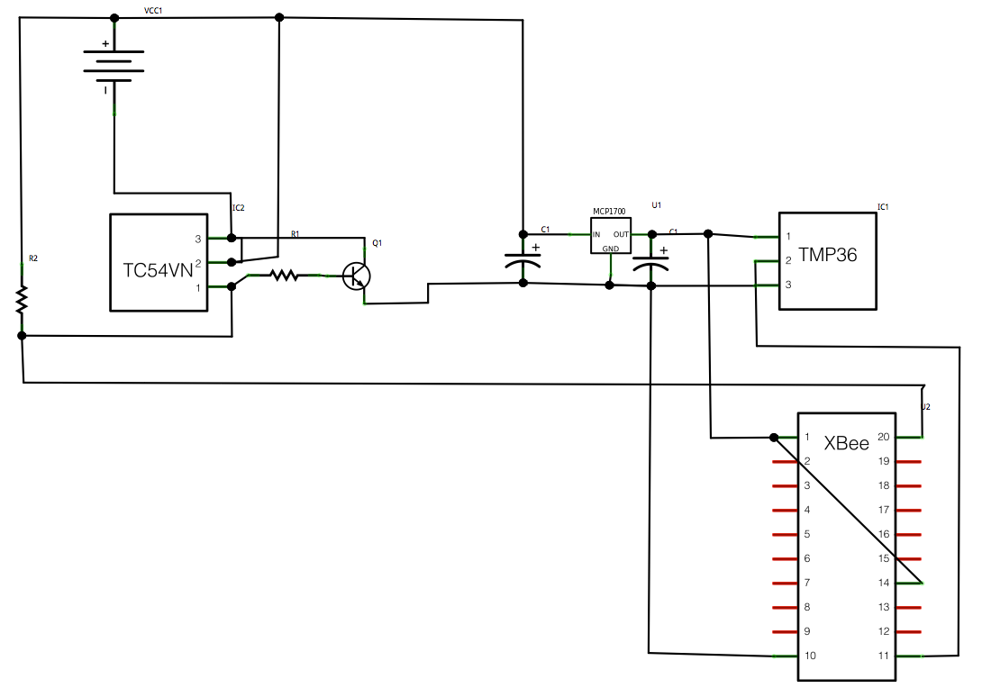
You’ll notice that I’m also running a wire to pin 20 on the XBee, this is A0 and will take an analog read from between the two resistors, they’re acting as a voltage divider which should mean I’ll be able to monitor the battery level and get an idea when I’ll need to change the batteries in advance. It should be possible to calculate, using V=IR, what reading I’ll get as the batteries approach 4.2V.
This seems like a good time for a bill of parts, so here goes:
I’ll also mention now that the Lady Ada article about TMP36 sensors was also really useful for teaching me how these work.
So that’s the power circuit and the temperature sensor all connected up to the XBee but you still need to program the XBee so that it’ll do something useful with that data. Again Lady Ada was really useful here, I followed the instructions on the Tweet-a-Watt which outline how to send current data via XBee. I used essentially the same programming to get my XBee to report the temperature and battery usage data from AD0 and AD4. I also bought the Rough Cut of Building Wireless Sensor Networks from O’Reilly. Unfortunately that only covers Series 2 XBees whereas I’m using Series 1, but the sections about how to wire an XBee up to USB for programming and what apps to use on the computer to speak serial to the XBee were really useful.
To connect the XBee to the computer I actually used an Arduino programmed with an empty sketch (basically void setup() {} void loop() {}). Pin 2 (DOUT) on the XBee was plugged into Pin 0 (RX) on the Arduino and pin 3 (DIN) on the XBee was plugged into Pin 1 (TX) on the Arduino. In this way I’m basically just piggybacking on the Arduino so that it provides a USB -> Serial interface. I then used the Serial Monitor in the Arduino IDE to send commands to the XBee and monitor the response. There’s more about this in the Tweet-A-Watt article. The program I sent to my probes was the following:
ATMY=1,SM=4,ST=3,SP=FF,D4=2,D0=2,IT=13,IR=1,ID=1234Which broken down means:
-
AT - Attention!
-
MY=1, - the ID of this unit
-
SM=4, - Sleep Mode SM (4 = Cyclic sleep)
-
ST=3, - Sleep Time (3 milliseconds after wakeup to go back to sleep)
-
SP=FF, - Sleep Period (0xFF - 255 x 10 ms = ~2.5 seconds)
-
D4=2, - enabling pin AD4
-
D0=2, - enabling pin AD0
-
IT=13, - number of samples (0x13 - 19 samples per packet)
-
IR=1, - sample rate (1ms between samples)
-
ID=1234, - the PAN ID for the network of XBees
Once that has been sent to the XBee it will go into sleep mode. This will mean that the XBee cannot be re-programmed unless you reset it. I actually haven’t figured out how to do that yet and so can’t modify the program on my XBees! I advise that you make sure you’re ready before sending it. It will sleep for 2550ms and then wake up, perform 19 samples with 1ms delay between each, transmit them and then go back to sleep again.
Once you’ve sent that to one of your XBees you can then place the module into the temperature sensing circuit and it should start transmitting temperatures. On the base station you would connect an unprogrammed XBee to an Arduino as above and send the following to it, this just sets the PAN ID and the modules own ID (to zero):
ATMY=0,ID=1234Now if you monitor the output on the serial connection you should see data being sent about every 2.5s. You can then use the XBee library for Arduino to parse this, or use the code for YAHMS as will be explained later in this series. If you are going to use the XBee library, be aware that the version available for download (0.2.1) actually contains a bug meaning it will give the same output for all pins, use the version in SVN instead which has been fixed.
Still to come, the relays and the base station, watch this space!
Comments
— Blog What I Made » YAHMS: Base Station
— Alfred